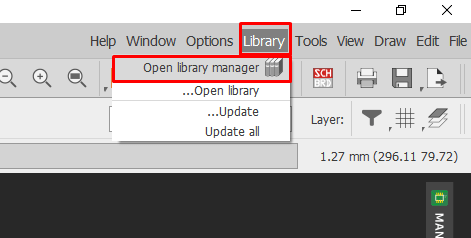
Making the smart plant Board
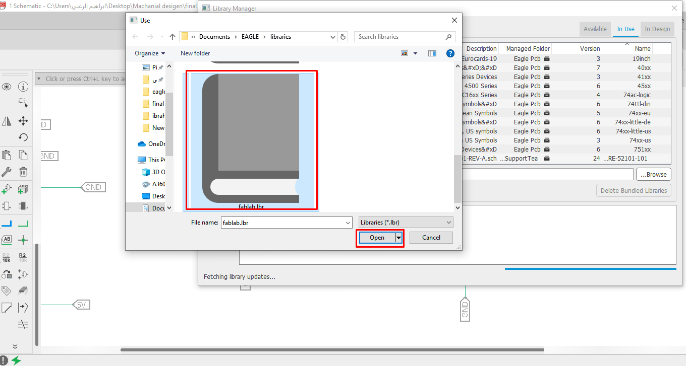
I used to create my board project, Eagle Program, and I downloaded the library fablab
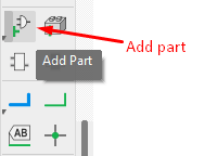
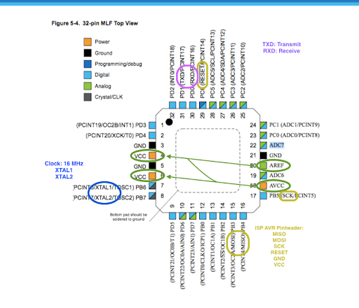
After that start adding circuit components, start with atmega328p as shown below in the image
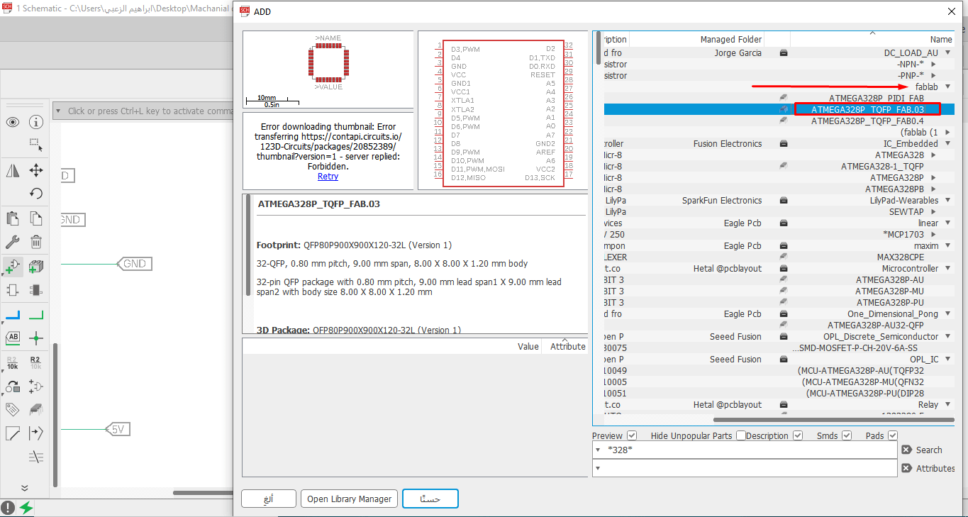
This data sheet for atmega328p cannot make the connections I need, and it is the same as the one used in the Arduino Uno.
These are the components I used in my Board
| components | Number |
| atmage328p | 1 |
| Resistors | 5 |
| 16MHZ crystal | 1 |
| Capacitors | 6 |
| LED | 2 |
| Potentiometer | 1 |
| Voltage Regulator | 2 |
| Pin Headers | - |
After adding atmega328p I made the appropriate connections and added a crystal 16MHz because crystal devices such as quartz crystal units and quartz crystal oscillators have high stability against an environment change such as temperature, they are used as frequency control devices in electronic circuits.
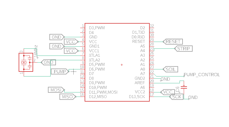
Then I added the pins as ports for the board that act as input and output for the board
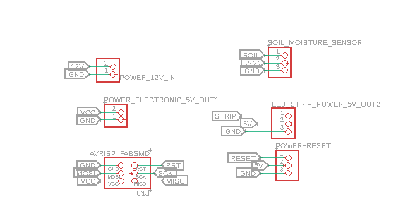
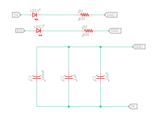
I have added two voltage regulators, they both work in the same function, which is converting from 12 volts to 5 volts, but one is to feed the atmage328p and the other is to supply the LED strip with 5 volt power and this voltage regulator distinguishes itself that it can withstand up to 3A
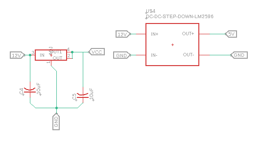
And I added 3 capacitors in parallel and the function of maintaining the stability of the circuit. I also added 2 LEDs, one of which is connected to the sck to give me a flash when programming and the other with 5 v. for sure that the electricity has reached the board.
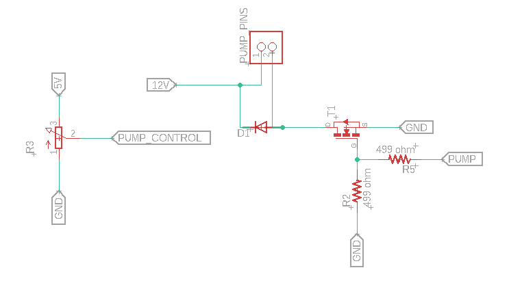
the pump control.Where I can control the strength of the pump by adding a Potentiometer by increasing and decreasing the voltage from 5v to 12v in addition to the MOSFET as shown below.
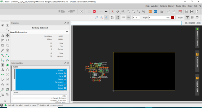
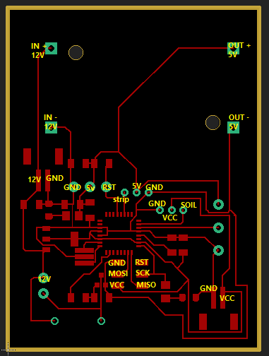
Now that you have finished connecting the circuit components together, it is time to make the design of the board
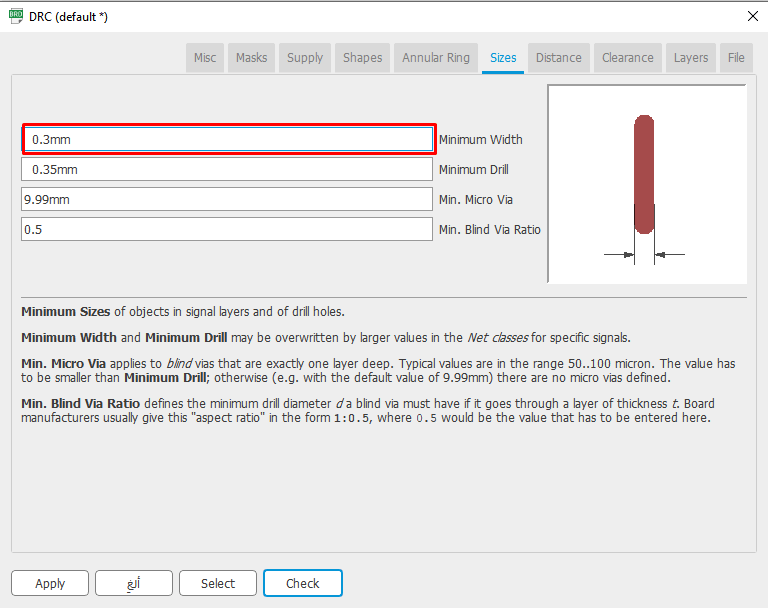
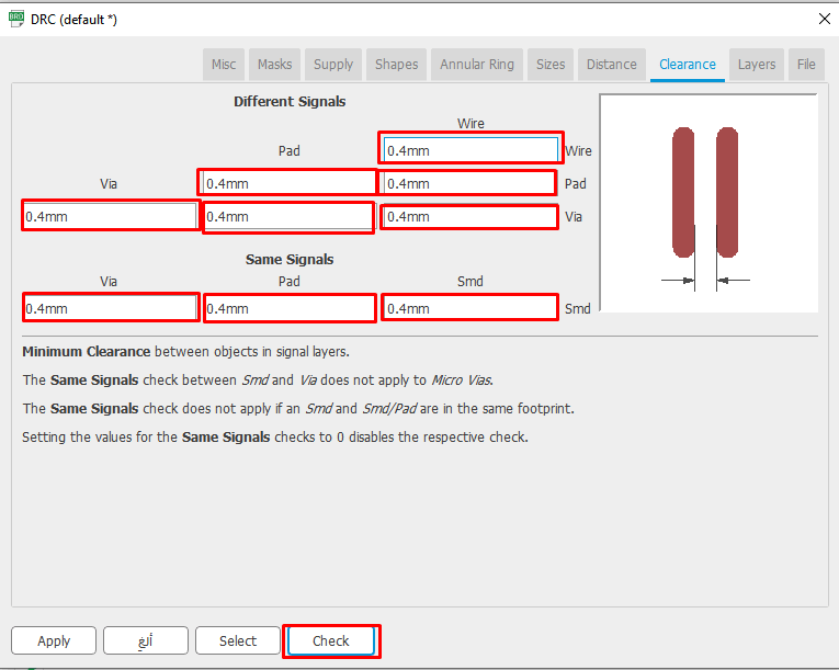
Before I started, I set the layers sizes
Then I started connecting until I finished
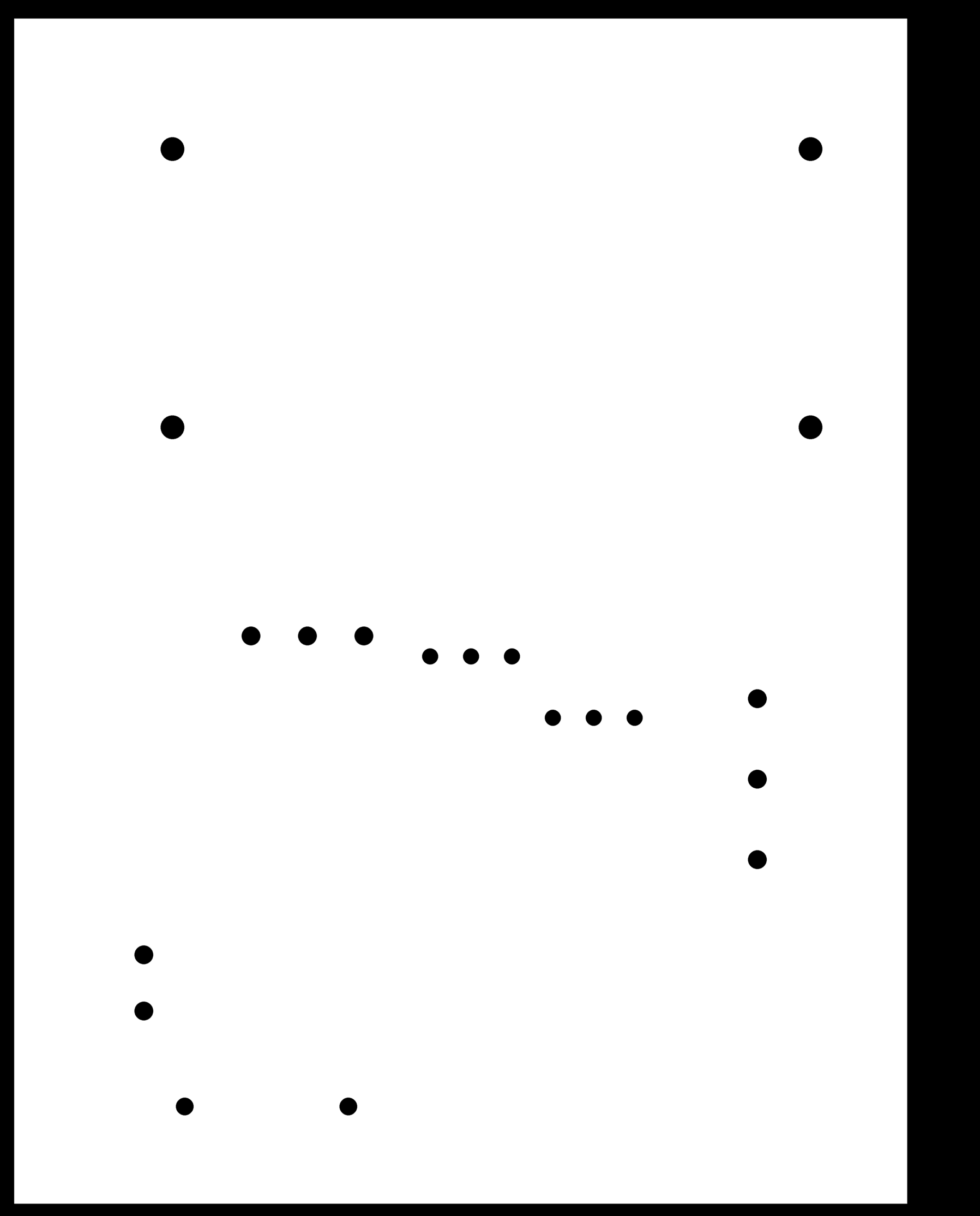
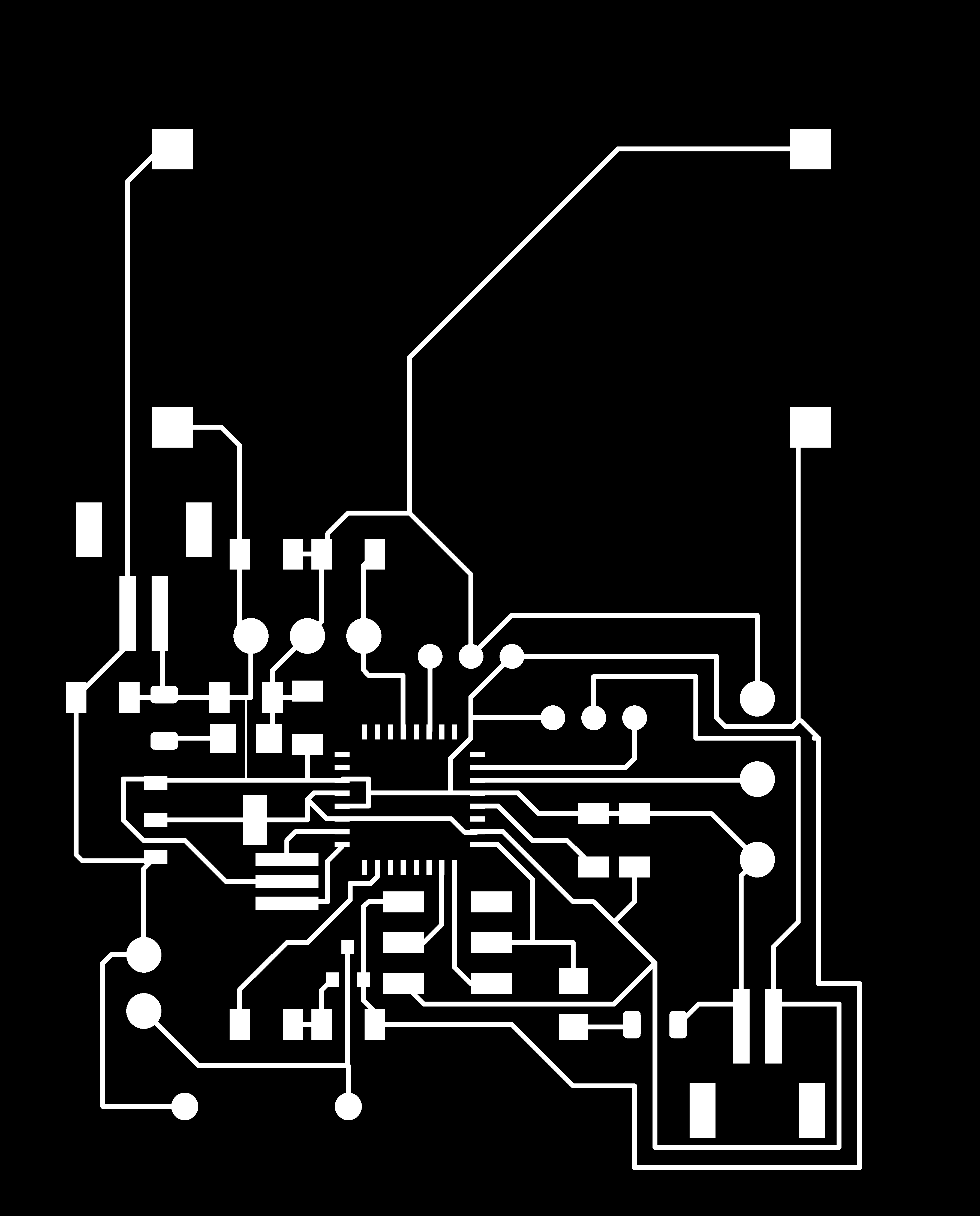
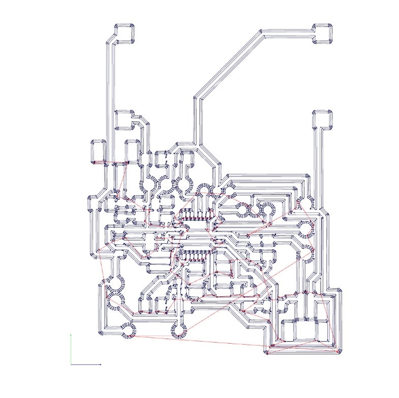
Then I export the design to get the following two pictures of drilling tracks and cutting the board frame
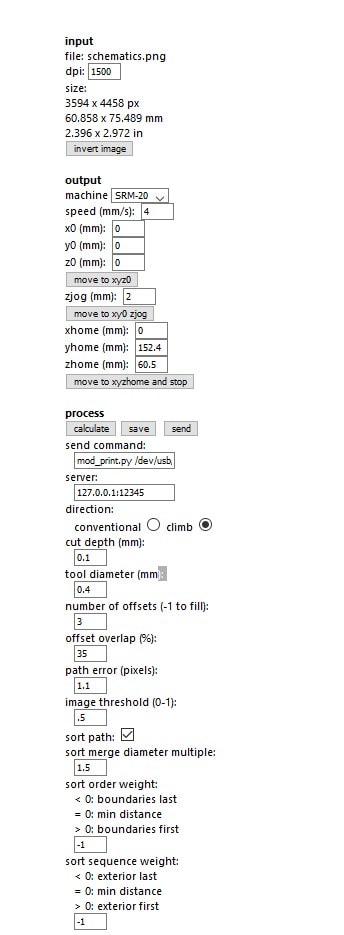
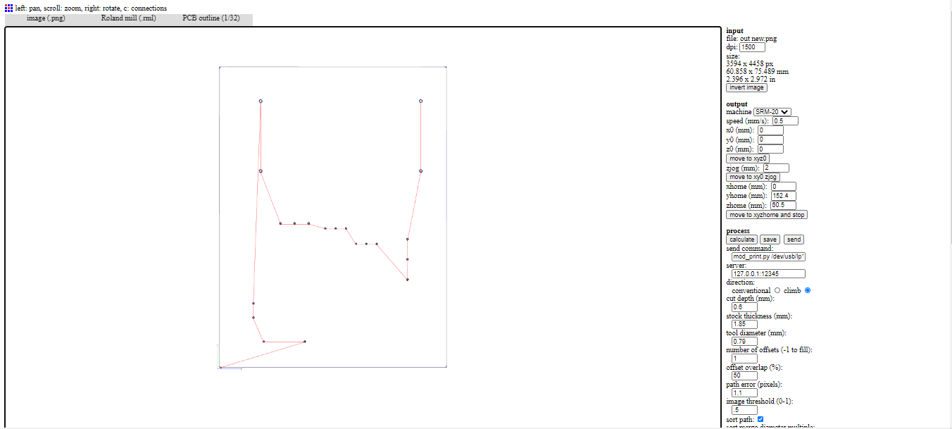
Fab modules
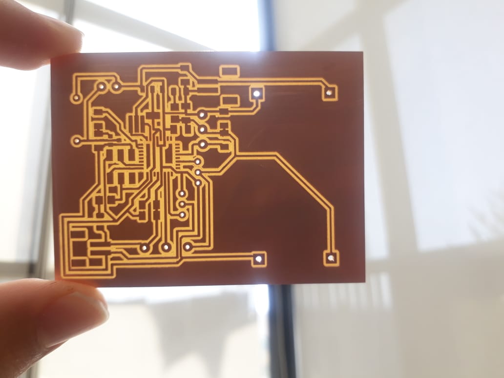
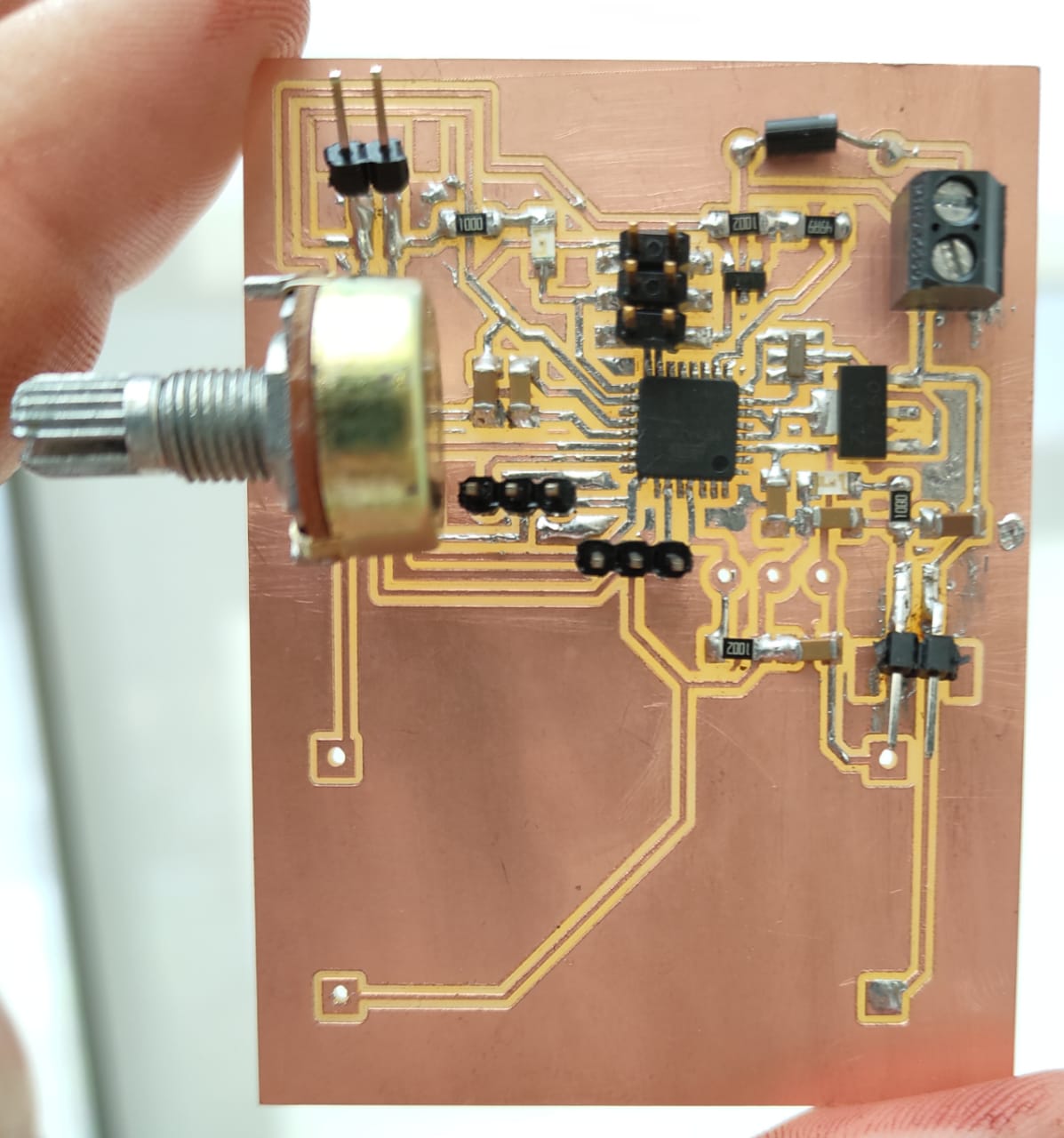
Here are two pictures of my board before and after welding
programming my board
you can download Gcode click here
you can download schematics click here